|
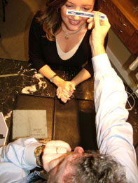
Are you using a millimeter ruler for PD's and fitting heights; does it define your expertise? As an optician or para-optometric, do you feel threatened by the number of digital measuring devices that you have seen or read about? I’ve had this discussion with many opticians and para-optometrics lately and here’s what I’ve heard. Yes, the Internet and new technology are placing new demands on optical staff everyday. Many have suggested that they can do “just as good a set of measurements” with a mm rule. Some say that these devices will replace them in the office. Others say it takes too much time. I say “hoooey”.
I look at the variety of iPad based and free standing floor or desktop devices as a way to free us up to do what we do best i.e., recommend and sell the best of the newest styles of frames and the best of materials, designs and treatments in lens technologies. Factoid: the average optometric office receives 50-60 percent of its gross revenue from Optical. The other fact about this office is that eye exam revenue and lens sales revenue are equal. So, why not consider investing in the technology of optical if a major revenue source is that side of the practice?
Besides, who benefits? Each office’s Optical group increases their expertise, patients are better measured for digital lenses where a new level of precision is being promised and the patient receives the best marriage of new technologies. Want these devices to work faster for you? That requires practice and use with every patient. Get good at it and it will make a difference. Moreover, the technology identity meets the identity of a digitally enhanced lens.
In 1980 I wrote a paper about the reasons to switch to a Pupillometer and get rid of the mm rule. Sound familiar? Well, (almost) all of you will agree that the Pupillometer delivers a more consistent PD across all levels of expertise in the office and it hasn’t gotten anyone fired. In fact, the more capable one becomes, the more valuable you become for an office. If anything, it gives you the opportunity to change jobs rather than losing it.
Here’s the paper as a historical exercise. In 1980, this study was supported by an educational grant from Varilux Corporation. It is surprisingly similar to the issues today for the optician and probably what the optometrist felt when auto refractors were introduced.
Comparing Methods and Techniques for Interocular Distance Measurement
Taking an interocular or interpupillary distance (PD) measurement is an everyday occurrence in any optical shop. There is, however, a running argument as to the most correct or accurate procedure. We all agree that a PD measurement is important, yet of all instruments available to us is one more accurate than another? Father Cherubin began such discussions with La Dioptrique Oculaire in 1671. His device was a pair of compasses and a looking glass.
A variety of instruments now aid in the task of obtaining a PD. They range in complexity and reliability. This report will compare six instruments and explore their strengths and weaknesses.
The PD is the distance between the centers of the entrance pupils of the eyes. It is commonly said that this corresponds to the line of sight or so closely approximates it as to be considered one and the same. Perhaps for low-power prescriptions this is acceptable. Aphakic, progressive, addition prescriptions greater than 4.00D warrant a more specific measurement of the line of sight.1.2
The average eye has a pupil that is not centered within the cornea, and the visual center is not centered within the pupil. Simply stated, therefore, geometric measurements do not reflect correct measurements of the distance between the parallel lines of sight. Approximately 65 percent of 500 left eyes had their visual axis at or within 0.5mm of the corneal apex as measured by photoelectric keratoscopy.3
The most accurate PD is the measurement of the distance between the visual axes of the eyes with the eyes focused at infinity. The accepted method of measuring the PD is by using a millimeter rule.4
Errors from the Accepted Method
The following are errors induced by the accepted method of using a millimeter rule to measure PD:
(1) Parallax introduced from the difference in-patient and practitioner's PD.
(2) Anisocoria, or a difference of pupil size in each eye.
(3) Visual axis PD versus geometric PD.
(4) Actual near point when measuring the near PD.
(5) Asymmetry of the face requiring monocular decentration.
(6) Invisible pupil margins as encountered in patients with dark eyes.
(7) Vertical differences of the two eyes.
(8) Poor reproducibility of the results.
(9) Lateral head or ruler movement while measuring a PD.
Based on my data, variations of 1 to 5mm in measured PD are possible with a millimeter rule, because the examiner or patient moves while the PD is being taken. A lateral (horizontal) movement of 1.5 inches by the examiner or patient or a combination of both will produce an error of 1 mm. It is possible that movements of up to 5 inches would be encountered; the error then would be in excess of 3mm. Instability of the rule on the patient's nose, examiner motion or patient motion all contribute to such error.
Lateral movements by dispensers are common. Amblyopic dispensers have interesting techniques for taking PDs. As they are able to sight with only one eye, a horizontal movement of 5 inches is not uncommon. This paper compares geometric and visual axes PDs. An eye looking directly at a point source of light will reflect that light reflex at the corneal apex, and that point can be considered one in the same with the visual axis.
 |
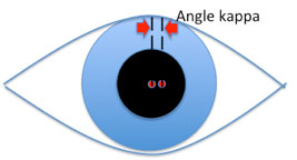
Angle kappa is the name for the angle between the pupillary axis and the visual axis. This point occurs at the entrance pupil and varies from individual to individual. The average angle is 5 degrees for an adult and up to 10 degrees for children and hyperopic patients. Myopic patients show smaller differences.
The position difference of the visual axis from the optical axis can be calculated. Assume the distance separating N (nodal point) and C (entrance pupil) is 4mm (emmetropia). Solving for 0, which is the change in PD using angle kappa, if 0 equals 4 tan k, then 0 equals 0.35mm for an angle of 5 degrees and 0.70mm for an angle of 10 degrees. Therefore, for the two eyes the error is 0.70 to 1.40mm; the visual axis PD should be smaller than the geometric PD by an average of 1mm?
A recent study determined the PD rule had a mean difference of 2.11 mm and a standard deviation of 1.745mm8 when compared with the corneal reflection pupillometer (CRP) in near PD measurements. Correct centration gives the best reproduction of the refraction if the phoropter or trial lens is properly centered on the eye, i.e., no prism induced. Strong powers, especially cataract lenses, require proper centration; however, they must be within the guidelines of "induced thickness." Excessive decentration of high plus or full field aphakic lenses creates excessive thickness and might produce different thicknesses between right and left lenses. Progressive addition lenses require precise monocular decentration for the success of the lens.
Methods
The first part of this report describes testing the accuracy of the PD measuring instruments. The second part covers use of each instrument, with various operators testing one individual. Part 2 tests monocular PD asymmetry and asks: What part of the population should actually have their lenses decentered for each eye instead of a binocular PD divided by 2?
Part I
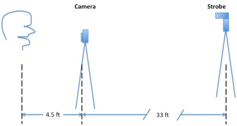
Each of the 85 individuals was tested with six PD measuring instruments or devices. Accuracy was checked using a slit-lamp chin rest upon which a millimeter rule was fixed. A 35mm single-lens reflex (SLR) camera and electronic strobe were used as a recording device.
The individual being tested was photographed with his head in a fixed position, sighting above the camera to a flag on the strobe 33 feet away. In this way the camera (4.5 feet from the subject), using a 105mm portrait lens, was able to photograph the light reflex of the flash and the millimeter rule at the same time in the same reference.
 |
Using the black and white negative as a slide, the image was projected on a flat wall. All sides of the slide aperture projected were measured to be sure that the projector was at right angles to the wall and the image was not distorted or altered. Measurements were done with the image three times actual size. Using a drafting caliper (compass), the reflex PD and millimeter scale were compared. By having the subjects look slightly superior and at an object greater than 20 feet away, convergence was negligible.
The last step was to correlate the data and decide which device is the most accurate for binocular PD measurement. The PD from a millimeter rule had a mean difference of approximately 1mm (originally predicted), and the measurement of departure from the mean was 0.65mm (standard deviation).
The Essilor CRP has a mean difference of approximately 0.25mm ±0.4mm with the lowest variance of 0.15 recorded. The Bausch & Lomb PD gauge had a large mean difference and deviation (1.9 ± 2.4mm). The AO Grolman device tests only slightly better than a millimeter rule 0.92 ± 0.63mm. The basic pupillometer is on par with the Grolman device 0.89 ± 0.66 mm. It can be said that the Essilor CRP provides the most accurate measurement, and in fact it has the most repeatable results.
At this point it can be said that the data is a fair representation of one person's ability to use various PD devices. Therein lies a problem: the consistency of the person taking PD measurements. What happens at the dispensing table, and what is the reliability of these devices in a variety of situations? Part 2 of this paper looks at this question, with 26 dispensers or assistants using the PD.
Part 2
The author traveled to various local opticians' and optometrists' offices. Using the same five devices in Part 1, a sample 26 dispensers were asked to measure the author's PD. The CRP usually was most accurate. This is significant, as the CRP shows the most reliability for providing repeatable results with the smallest deviations. All instruments or devices show the possibility of being 1 mm off, with the millimeter rule showing the least reliable results.
Since each participant was taught the proper use of each device and then results were taken, the best results came from use of the CRP, even with a minimum of training. Moreover, all the devices except the CRP show an average error exceeding 1mm and approach a 2mm error an equal number of times. The Grolman device shows the largest variance (1.68) and therefore the poorest repeatability; compare it to 0.106 for the CRP with a mean error of only 0.25mm.
Standards today are revised; ANSI z80.1-1972 is horizontal prism two-thirds, or if greater, the major reference point is ± 2.5mm of the specified PD. If the PD measured was 2mm off initially, by using a millimeter rule, the net cumulative error might be 4.5mm or more. However, you were not aware of the original 2mm error.
A corneal reflection pupillometer is worth the investment. In return, the practitioner or dispenser has an instrument that is easily mastered, provides accurate and repeatable results, adds professionalism to the practice and assures the same care at the beginning of the dispensing cycle that final inspection of the finished spectacles gives at the end of the dispensing process.
Finally, a test sample of individuals was studied for facial asymmetry. Some attention must be given to monocular decentration. Binocular PD's do not induce many problems, as the majority of prescriptions are anisometropic by no more than 0.5 to 1.000. Horizontal imbalances seldom exceed tolerable limits.
However, in high-powered prescriptions (cataract spectacles) and progressive addition lenses especially, the need for proper monocular decentration is essential. "If the major reference point is not centered in front of each eye, as the wearer looks down and inward the eye will follow a path next to progressive corridor.6
Since facial asymmetry is the rule rather than the exception and the Essilor CRP was found to be the most accurate measuring instrument, the CRP was used by many practitioners to sample a portion of the population for average facial asymmetry. The CRP accurately assesses asymmetry because the instrument rests on the nose in the same manner as a plastic frame.
Various offices and clinics around the country provided data for a study of 355 individuals. We found that: (1) Monocular PD asymmetry varies about 2mm (2 standard deviations). (2) The average person's eyes differ in monocular PD by 1mm. and (3) Men show slightly more difference than women. Of the total population, 88 percent have a monocular PD asymmetry of up to 2 mm.
Conclusion
Facial asymmetry must be considered when fitting special lenses. Progressive addition lenses require special fitting of their MRPs to allow for proper use of the distance, progressive zone and near portion of the lens. Since precise measurements are needed, the instrument of choice should be the Essilor CRP. The CRP provided the most accurate measurement of visual axis (z axis) PD. The CRP showed the most repeatable and reliable results. Since monocular PDs are required for specialty lenses, the instrument of choice is the CRP.
References:
1. Frieder, P.M., Accurate PD's may not be the answer. Focus, 1 (2):3435, 1979.
2. Drew, R., Invisible multifocals: FuIture shock in opticianry. Optical Management, February 1980, pp.10-31.
3. Tomlinson, A., Schwartz, C., The position of the corneal apex in the normal eye. Amer. J. Optom. And Physiol. Optics, 56:236-240, 1979.
4. Brooks, C.W., Borish, I.M., System for Ophthalmic Dispensing. Chicago: The Professional Press, Inc.,1979, pp. 28-29.
5. Borish, I.M., Clinical Refraction, ed. 3. Chicago: The Professional Press, Inc., 1975, pp. 424-426.
6. Brooks, C.W., Borish, I.M., A potential problem in progressive addition lens placement. Optical Index, 54(1 ):116-118, 1979.
7. Alexandre, M., Measuring monocular PDs. The Optician, March 22, 1974.
8. Hoeft, W.M., Martin, J., Lee, T., Three ways to measure PD. Rev. Optom., Jan. 15, 1980, pp. 53-56.
9. Recommended Procedures for Dispensing the Welsh Four Drop Aspheric Lens. San Marcos, Calif.: Armorlite, Inc.


